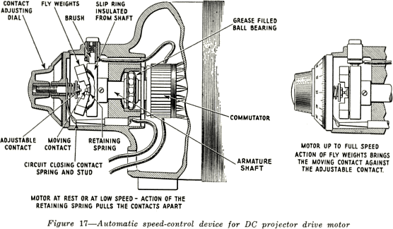
The action of this device can best be explained by referring to Figure 14. One end of a
resistor in the field circuit of the motor is connected to the moving contact through the
slip ring and brush. The other end of the resistor is connected to the stationary contact.
As the motor speeds up, the fly weights move out (away from the shaft) and bring the
moving contact closer to the stationary contact. When the motor reaches a certain speed
the moving contact touches the stationary contact, and the resistor in the field circuit is
short-circuited. The position of the contacts under this condition is shown in the right-hand drawing of Figure 17. This allows the current in the field circuit to increase and the
motor "slows down." When the motor slows a little, the contacts open and the resistance
is again connected in the field circuit, decreasing the field current which increases the speed of the
motor. This continues, the contacts opening and closing very rapidly, and the motor
rotates at a practically constant speed. The position of the stationary contact can be
varied. It can be moved in or out by rotating the dial at the end of the motor. If the dial is
rotated in a clockwise direction it moves the stationary contact closer to the revolving
contact, a connection is made between the two at a lower speed, and the motor will run at
a slower speed. If the dial is rotated in a counter clockwise direction the contacts are
moved further apart, and it then becomes necessary that the motor run at a higher speed
before the contact is closed and the motor is held at this higher speed.

When the motor speed is properly adjusted for a film speed of 90 feet per minute,
the dial-reading opposite the white line nearest the white dot on the top of the speed-regulator housing should be carefully noted and preserved for ready reference, so that the
dial may be quickly and accurately reset in case it is accidentally disturbed. The dial figures are for calibration only, and do not indicate either motor or film
speed.
8
