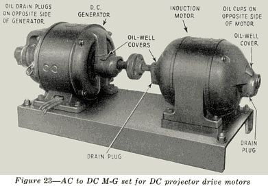
The equipment consists of two identical M-G sets; two motor starting boxes, one for
each M-G set; a generator control panel; and two push button stations, one for each M-G
set.
The power for driving the motors is supplied through a three contact, magnetically
operated line switch, called a "contactor." Figure 24 is a picture of this switch. It is
operated by pushing the "Start" button of the push-button station shown in Figure 22.
When the line switch closes, it also closes an auxiliary (holding circuit) contact which is
connected across the "Start" push-button so as to keep the operating circuit closed when the "Start" button is released. The motor starting boxes do not
contain fuses, but contain instead an over-load switch which turns off the power to the
motor in case of trouble. If, for any reason, the motor draws excessive current, the
heating of a thermo-element in series with the motor line causes a spring to bend and
trip a switch which in turn opens the circuit to the operating coil of the motor line switch.
It will not then be possible to start the motor until this switch has been reset by hand.
The reset is operated by either pulling up a lever which protrudes from the right-hand side
of the starting box or by pulling on a string which hangs from the bottom of the box.
(There are two styles of starting boxes used and the operations of the reset is the only
real difference.)

Porcelain shields called "flash guards" are mounted over the contacts to
prevent an arc from occurring between two adjacent switch contact arms or points.
The DC power from the generators is controlled through the generator control panel.
At the top of this panel are located line switches for both generators (see Figure 25) . Just
below, and associated with, each line switch are two 30 ampere fuses for the protection of
the DC circuit from serious overload. At the bottom of the panel are two generator field
rheostats for controlling the voltage of the generators. A DC voltmeter is mounted at the center of the panel and indicates the
DC line voltage (generator voltage).
17
