Figure 48 shows a schematic diagram of the galvanometer and optical system. The light from
the lamp is focused through a condensing lens onto the mirror of the galvanometer. The light stop between the lens and the mirror is for the
purpose of cutting off the fringe of distorted light so as to give a clear cut beam
of light. The galvanometer window is tilted at a slight angle to keep the light
reflected from its surface from entering the optical system. The reflected light
from the mirror passes through the cylindrical lens, which condenses the light in
one direction only. It then passes through a spherical condensing lens which
reduces the beam size still more. The beam from this lens is focused on the slit
in the aperture plate (this slit is 0.003 of an inch wide). The light which passes
through the aperture plate slit is focussed on the film through a microscope objective lens system. This objective reduces the size of the beam by a 4 to 1 ratio in
both directions so that the resultant beam on the film is 0.070 of an inch long by
0.00075 of an inch wide.

When the mirror is at rest, only one-half of the sound track is exposed. The
other half of the light beam is cut off by a screen. When the mirror is moved to
its extreme position in one direction, the light beam is shifted off of the screen so
that the beam covers the entire sound track. When moved in the other direction to
its extreme position, the beam moves over so that it is cut off entirely by the screen
and strikes no part of the sound track. When referring to the extreme position
which the mirror moves it is not meant that this extreme is the maximum movement which can be obtained by the mirror, but only the maximum position to which
it should ever move when recording. When the film moves through the recorder
it is exposed to this fine line of light which varies in length as the mirror vibrates in
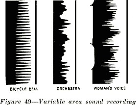
response to the sound currents flowing through the loop supporting it. When the
film is developed the part of the film which was exposed to the light beam will be
opaque while the remainder of the sound track will be transparent. See Figure 49.
The juncture of the opaque and transparent parts of the sound track form a wavy
line which is practically an exact representation of the sound pressures of the original
sound waves. When this sound track moves through the sound head of the projector
the amount of light passing through the film will vary with the width of the transparent part of the track. This varying amount of light produces a varying current
through a photo-electric cell. The effect of this current is amplified in a vacuum
tube amplifier and the amplified variations are sent to the loud speakers which reproduce the sound.
68. Synchronizing Sound on Film. -The sound film is usually run on an entirely separate machine from
the camera for practical reasons, and the two films must be so synchronized that when they are printed
together they will be in synchronism throughout the length of the film. This is accomplished by running
the camera and the recorder at exactly the same speed. They are both driven by synchronous motors
connected to the same power supply, and this keeps them always in synchronism. Some kind of
marking is required so that the picture and sound track can be lined up for printing. This is sometimes
taken care of by marking the film by means of a small marker lamp which shines on the film outside of
the sprocket holes. Since the sound gate of the projector is 19 frames from the picture in the light
aperture it is necessary to displace the sound track by 19 frames when they are printed together. The
advantage of sound-on-film is that the sound will always be in synchronism with the picture if the
projector is properly threaded. The breaking of the film does not interfere with the synchronous action,
so that a blank patch is not necessary.
6
