100. Threading the PS-14 and PS-16 Sound Heads.- Figure 67 shows a PS-16 sound head properly
threaded. After leaving the take-up sprocket of the projection head the film passes down
through a slot in the frame into the sound head. From the slit it passes through the sound gate,
under the idler roller at the bottom of the gate, then to the left over the impedance roller, and
from the roller to the constant speed sprocket. There should be a two sprocket-hole loop
between the projection
head take-up sprocket and the sound gate.
 After leaving the constant speed sprocket the film
passes to the left to the sound head take-up sprocket. There should be a four sprocket-hole
loop between these two sprockets. From the take-up sprocket the film passes to the lower
magazine. The purpose of the sound head takeup sprocket is to prevent any irregularity in the
action of the take-up reel from being transmitted to the constant speed sprocket.
After leaving the constant speed sprocket the film
passes to the left to the sound head take-up sprocket. There should be a four sprocket-hole
loop between these two sprockets. From the take-up sprocket the film passes to the lower
magazine. The purpose of the sound head takeup sprocket is to prevent any irregularity in the
action of the take-up reel from being transmitted to the constant speed sprocket.
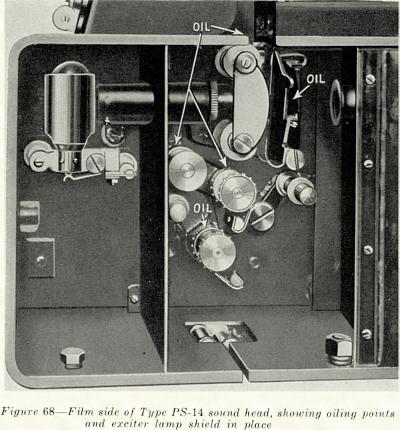
101. Oiling Points on the Film Side of the Type PS-16 Sound Head. (Used with the Simplex Projector).-The oiling points on the film side of this sound head are the same as those of the
type PS-14 as shown in Figure 68 (with the exception of the hole in the center plate of the
sound head above the sound gate), and are indicated by red circles. These oiling points, aside
from the oil holes in the pad rollers and the two rollers on the sound gate, are four in number
and are situated as follows:
11
