Types PG-1 and 2 have all units-exciter lamp rheostats, ammeters and relaysmounted in the
amplifier rack, the only control on the projector being the fader actuating switch.
One more switching device is used in connection with the above mentioned controls. This is
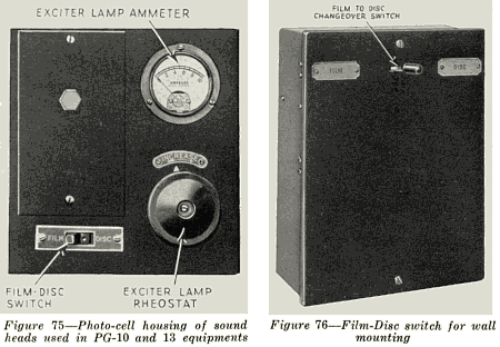
the "Film-Disc" switch, illustrated in Figure 76, used on Types PG-1, 2, 3, 4, 6, 7 and 8. The
function of this is merely to change one side of the output from the film or disc circuit, so that
one or the other is always connected to the input of the amplifier. Since one side of the
circuits from film and disc outputs is a common lead, only a single-pole switch is necessary.
One such switch is provided for each projector. As mentioned before, this is mounted on the
sound head on Types PG-10 and 13. All other equipments are provided with
 a special switch box, which serves as a terminal box as well. It contains terminals for both
sound head and turntable output circuits and necessary resistors and potentiometers for
balancing film and disc output, so that each will be equal on the same projector. One form of
this box is illustrated in the figure. This type is placed on the front wall of the projection room,
near the operating side of the projector it controls. Another type is mounted on the sound head
on top of the photo-cell housing. Both serve the same purpose and have similar types of
switches. These are off in the center position. On Types PG-10 and 13 this switch is mounted
in the photo-cell housing on the sound head, and is similar in purpose to the others, although
different in appearance. It is a standard type of tumbler switch.
112. Rheostat and Potentiometer Connections.-Rheostats and potentiometers, as was
mentioned in section 14, are nothing more than wires of relatively high resistance, much higher
than those used ordinarily in electrical circuits, so made and connected in a circuit as to vary
the amount of current passing through it.
3
