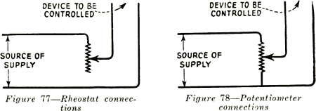
Consider the application of the rheostat to the control of the exciter lamp.
It is connected in series with the load, which in this case is the exciter lamp filament. That is, the connections are made to one end of the continuous length of
resistance wire, and to the movable arm. Any change in setting of the rheostat
knob makes a corresponding increase or decrease in the amount of resistance
in series with the lamp. This causes an increase or decrease in the amount of
current passing through the circuit, since increasing the resistance decreases the
current, and vice-versa, when the line voltage remains the same. However, the
voltage across the lamp itself is decreased when resistance is inserted, the resulting
current in the circuit being indicated on the ammeter. Figures 77 and 78 show
both rheostat and potentiometer connections of two similar circuits.

For very fine and smooth control of voltage over a wide range, a potentiometer
is much better adapted than a rheostat. Potentiometers are similar in appearance
and construction to rheostats, the difference being only in the connections. Section
14 mentioned the similarity in action between a potentiometer and a water pipe
with valves tapping off water at different distances from the pump, or source
of pressure. The potentiometers are made with resistance taps, so that their
action, when connected in the circuit properly, as in Figure 78, is similar to the
water system. With potentiometer connections it is possible to obtain any voltage
from maximum to almost zero, because any "pressure" may be tapped off, while to
obtain the same range of control with rheostat series connections, it would be necessary to use a much greater amount of resistance, thus making the device very
bulky and cumbersome.
113. Construction and Use of Exciter Lamp Rheostats.-Three types of construction are employed on the various rheostats used on the controls under discussion,
two of these being used for exciter lamp rheostats. Those mounted in input control panels (equipments in Classes II and III of the table) are made of resistance
wire embedded in vitreous enamel, with tapped points consisting of brass button
contacts projecting through the enamel in the form of a circle. This unit is made
with the enamel baked on in a round pressed steel plate. A rotating contact arm,
actuated by a handle, passes over the circular row of contact buttons. This entire
unit is encased in a pressed steel housing, as shown in Figure 79.
The rheostat used for projector mounting (Class IV) consists of a short
cylindrical form around which a length of resistance wire is wound. A rotating
arm with a contact roller mounted on the end of it passes over this wire wound
form, and is controlled by a handle, or knob. This whole unit, together with the
ammeter, is mounted on the sound head.
4
