115. Connections of Potentiometer Fader.-When it is desired to vary the voltage of the input
of an amplifier by means of a variable resistance so as to completely cut it off, or in this case,
to completely "fade out" the sound, a potentiometer is better adapted than a rheostat. With
connections made as shown in Figure 78, it is possible to change smoothly and rapidly from
maximum output to zero. When the sliding contact arm is at the point of the potentiometer
farthest from the one output connection a maximum voltage is obtained at the other output
circuit. As this arm is moved towards the end of the potentiometer at which the other output
connection is made, the voltage is reduced until it is finally brought to zero. At this point, the
output circuit is short circuited due to the fact that the sliding arm of the contact is resting
immediately above the other output connection.

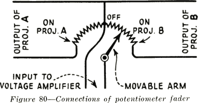
The fading potentiometer used on Photophone input control panels is, in effect, a double
potentiometer, connected as illustrated in Figure 80. In other words, its effect is that of two
potentiometers connected together, one being used to cut out the signals from one projector
while the second picks up where the first left off, and increases the signals from the second
projector as the movable arm moves through its travel. The output from the two projectors has
a common connection made to the center of a group of resistor units. The other connections
from the output of the two projectors are individually connected on opposite ends of this group
of resistors. The input to the amplifier is taken off at the sliding contact and at the midconnection of the potentiometer. Thus, when the resistor sliding contact is at the center of its
swing, there will be no input to the amplifier, as the input circuit has been short-circuited. If it
is on the extreme position to the right, the right-hand projector will be used and the other will
be out of the circuit. When at the extreme left of the swing, it will cut out the right projector
and the one on the left will be in the circuit.
116. Construction of Potentiometer Faders.-The potentiometer fader consists of a Micarta
plate about four inches square, on which are mounted a semi-circular row of brass button
contacts. For each one of these contacts there is one small resistor unit. These individual
resistance units are connected in series, one end of each being connected to the contact, and
the other end to the adjacent unit. The plate is mounted on the rear side of the input panel,
with a center shaft projecting through. The shaft is mounted so as to be centered on a threeinch round hole in the front panel. A name plate covers this hole, and the control
knob, with pointer, is mounted on the shaft after the plate has been placed. The moving
contact arm, made of spring brass, is on the front of the Micarta plate, and, therefore, just
inside the hole in the panel front. When the name plate is removed the contacts are exposed,
which affords easy access for cleaning. The potentiometer faders are shown in Figures 74
and 79.
6
