The potentiometer fader is in the "Off" position when the pointer is up. The extreme position
to right or left is the point at which the fader should be when operating the equipment.
The volume controls for various types of equipments are constructed in the same manner, the
difference being only in connections and location. The contacts
of all these units are cleaned by removing the knob and name plate, and applying a clean rag
moistened with Carbona.

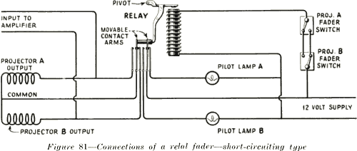
117. Construction and Operation of Relay Faders.-Types PG-1, 2, 10 and 13 do not use the
above mentioned fading potentiometers, the sound change-over on these types being
controlled by means of a relay. A relay is an electrical device by which circuits are controlled,
or switched, by means of a control circuit actuating an electro-magnet. The circuit controlling
the electro-magnet is entirely separate from the other circuits involved, the usual method of
control being to close the operating circuit, which actuates the magnet. This magnet attracts
an iron armature which mechanically makes or breaks one or more contacts. As applied to
Photophone faders, this device consists of a straight electro-magnet operated by the twelve
volt supply, from the storage batteries on PG-10 and from the low voltage generator on PG-1,
2 and 13 equipments. See Figure 81. This is controlled by two three-way switches, one
mounted on each projector. The electromagnet actuates an iron armature, which in turn
moves two movable contacts. These are insulated from each other and from the armature by
a small insulating block. These two movable contacts each normally make contact with one
fixed contact arm, when the actuating circuit is open. When the magnet is energized by
throwing either fader switch, the armature pushes the small insulating block, and the two
movable contacts are moved over so as to make contact with two other fixed contacts.
7
