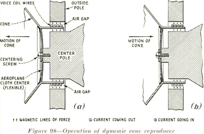
The moving coil has been carefully centered in the air gap so that no part of it may touch either pole
piece. This setting has been clamped by the centering screw. If the coil should touch either of the pole
pieces at any time when the speaker is operating, the movement of the cone would be interrupted and
distortion would result. Dirt in this recess would cause the same trouble. The speaker is protected with
cloth screens to prevent dirt from entering, and these screens should not be removed. Front and rear
views of this unit are shown in Figure 99.
The dynamic speaker used by RCA Photophone reproduces all frequencies in the audible range very
faithfully. The tonal characteristics are extraordinarily
natural. It is a superior mechanical achievement and a finely adjusted instrument, and while the
construction is rugged and strong, it should be handled on the stage, where such handling is
necessary, with as much care as possible.

148. Operation.- The dynamic loudspeaker operates on the same fundamental principles as those
underlying the action of an electric motor. If a coil or winding carrying an electric current is placed in a
magnetic field this coil has a tendency to move in a direction at right angles to lines of force in the field,
the amount of movement being proportional to the number of lines of force and the amount of current
flowing in the coil. The direction of movement depends upon the direction of flow of both the lines of
force and the current in the coil. When alternating currents of various frequencies are sent into the
voice coil of the dynamic reproducer the pulsations in one direction move the coil outward, and the
pulsations in the other direction send the coil inward, since the lines of force from the magnet poles are
always moving across the air gap in the same direction. This is true since the field is energized by direct
current. Figure 98 shows how this action takes place. The arrows
representing the lines of force always flow from the same pole, but the direction of current in the voice
coil changes constantly. Figure 98 (a) shows the current, and consequently the motion of the cone, in
one direction, and (b) the other. This results in -a rapid back and forth vibration of the voice coil, and
the cone attached to it, in exact correspondence with the pulsations of the currents in the voice coil,
which are the output of the amplifiers. The vibrations of the cone create sound waves which are a
reproduction of the variations of electrical energy set up by the running of the disc or film recorded
sound.
3
