Made available to visitors to The American WideScreen Museum by
Mr. David Johnson, Melbourne, Australia
Transcribed and edited at AWSM, Houston, Texas, U.S.A.
CINEMASCOPE IN THE THEATRE EQUIPMENT INFORMATION, INSTALLATION PROCEDURES, MAINTENANCE AND OPERATING PRACTICES
F O R E W O R D The motion picture exhibitor has been belabored with many conflicting statements and ideas concerning large screen projection, stereophonic sound and other new production techniques.
CinemaScope is ready for the theatre and it is now essential to dispose of any misunderstandings with clear, concise information. This bulletin, prepared by the Research and Development Division of Twentieth Century-Fox Film Corporation, under the direction of Mr. E. I. Sponable, answers the questions of the exhibitor, provides data, states equipment requirements and furnishes technical information so that CinemaScope may be readily introduced.
Second Printing
Revised November 1953
I N D E X
1.0 PURPOSE
2.0 WHAT IS CINEMASCOPE?
3.0 PROJECTION EQUIPMENT
3.1 Sprockets
3.2 Aperture
3.3 Sound Heads
3.4 Miscellaneous
3.5 Film Handling Equipment
3.6 CinemaScope Attachment
3.7 Projection Ports
4.0 SCREEN
4.1 Types
4.2 Hanging
5.0 SOUND
5.1 Loudspeaker Systems-Screen
5.2 Loudspeaker Systems-Surround
5.3 Amplifier System
5.4 Signal and Control for Surround Effects
5.5 Noise
5.6 Response
5.7 Subjective Tests
5.8 Phasing
5.9 Test Film
6.0 OPERATION AND FILM HANDLINGLIST OF ILLUSTRATIONS
Fig. 1 Film Dimensions
Fig. 2 Film and Sprocket Dimension Layout
Fig. 3 Release Print
Fig. 4 Typical Picture and Aperture Shapes
Fig. 5 Outline of CinemaScope Attachment 41-77-04
Fig. 6 Outline of CinemaScope Attachment 41-77-02
Fig. 7 Typical Distribution of Miracle Mirror Flat Screens
Fig. 8 Typical Distribution of Miracle Mirror Tilted Screens
Fig. 9A &9B Sound Reproducing Frequency Characteristics
Fig. 10 Photograph of Typical Sound Head and
CinemaScope Attachment on Projector
Fig. 11 CinemaScope Release Film Leader
Table I Projection Table - Picture Size
Table II Screen Widths and Depth of Curve for Curved Screens
This literature has been prepared to provide the distributor, exhibitor and operating personnel with some basic understanding of CinemaScope, to indicate equipment changes, to describe installation procedures, apparatus adjustment, differences in handling practice, precautions which should be observed and certain operating features. These notes have been carefully prepared on the basis of all present knowledge with the idea of facilitating an orderly preparation and smooth operation for a showmanlike presentation of CinemaScope product. It is likely that these preliminary instructions will be subject to some modification from time to time as the occasion warrants.

CinemaScope is a completely engineered system for the practical presentation of wide screen pictures combined with true stereophonic sound and so designed as to provide the greatest approach to realism in motion picture story telling which has yet been achieved. This realism is possible because the CinemaScope scheme permits using lenses during the photography which gives the most natural perspective; the angles of view in the presentation of CinemaScope approach that to which we are accustomed in life and the effect of stereophonic sound is to assist in bringing the performance to the stage or area before the audience. All of the factors of depth perception except stereoscopic vision are used but two inter-locking projectors and films are not required. CinemaScope is not a so-called 3-dimension system. CinemaScope is not a temporary expedient of wide screen presentation such as has been used to some extent on product which has not been produced with this in mind, nor is the stereophonic sound associated with CinemaScope any engineering compromise to hurry release or to be first in the field for exploitation purposes. All films produced by 20th Century-Fox in CinemaScope have been specifically staged and photographed with this medium in mind.
The screen shape (not just the size) has been chosen as the closest practical approach to peripheral vision2 as it seems possible to do today, without putting a considerably greater cost burden on the exhibitor than is required for CinemaScope. It can be demonstrated that CinemaScope gives an excellent presentation for nearly all the seats in a theatre. Further, screen shape is sufficiently different from past product so that it is noticeable to the audience rather than merely going part way in this regard.
1. Stereophonic sound is a method of recording and reproduction which, in effect, recreates the original sound performance on the screen as though the performance were actually there. Stereophonic sound requires the use of a multiplicity of microphones with separate and individual recording channels And records for each; the reproducing system requires the same number of separate channels and loudspeakers. Stereophonic sound includes, as one distinct feature, the directionality, or localization, of sound sources corresponding to the visual location of the source on the screen but has additional definite and desirable features not otherwise obtainable. Directional, or pseudo-stereophonic, sound is recorded with a single recording channel, as has all past motion pictures which have had worldwide release, and employs a multiplicity of reproducing channels and loudspeakers. It has only the feature of directionality and whatever effects of perspective might be synthesized.
2. Peripheral Vision is what we see at the sides when we look straight ahead.
The CinemaScope picture has sometimes been referred to as a "ribbon of picture"; this is a false statement because it strongly implies that the picture has very little height and great width. The height of any picture in the usual theatre is determined by the sight lines of the house and it is emphasized that every effort should be made to continue at least the same picture height in the theatre as presently is used. No picture system or any other aspect ratio can put any greater picture height in the theatre than is dictated by the sight lines. Once the height is fixed the width for CinemaScope is determined by the aspect ratio, i.e. by multiplying the height by 2.55. Under the stated circumstances the resulting picture will be roughly twice as wide as the old picture for the same height. If a situation exists in a particular theatre which positively limits the picture width, then the height is determined by dividing the maximum width by 2.55. In dealing with a number of small theatres it has been found that, with thought and engineering ingenuity, it was possible to install a screen of considerable width and the resulting picture height for CinemaScope was essentially the same as the prevailing height in the theatre. Actually, if the existing projection lens is used with CinemaScope the resulting screen image will have greater height than the conventional picture because the 35mm film is being used to greater advantage by employing a frame with 19% greater height.
The story telling must be handled differently and approaches that of legitimate stage technique but still maintains the unique feature of motion pictures where scenes can be rapidly changed at will. The closeup is used less frequently but is as important as ever and the intimate scene is not ruled out.
In photographing the picture a special optical attachment, technically described as "anamorphic", is added to the front of the conventional camera lens. The anamorphic attachment "looks" at a wider picture than the conventional lens but does not in the least way affect the height, the result being as though the picture were photographed in a horizontal direction with a very wide angle lens but with an ordinary lens in the vertical direction. Observation of the image on the negative, or the print made therefrom, will show that the image is squeezed in the horizontal direction. All objects seem to be thinner than they should be. By adding to the projector a similar optical attachment in combination with the existing projector lens which has precisely the opposite effect to the taking lens, the image is restored optically to its correct proportions and the picture on the theatre screen is a true reproduction, in all of its proportions, of the original scene. In this way it is possible to get a very wide picture on a standard piece of 35mm film and use all of the available area of the film. In order to provide as large an image on the film as possible, to reduce the magnification required in the theatre, to maintain resolution, to minimize grain and to provide space for the sound tracks, it has been found entirely practical and good engineering to reduce the size of the sprocket holes on the film. The reader can easily observe that the sprocket holes have less width than the present standard film and that they are located near the outer extremes of the existing sprocket holes. (See Fig. 2)
Since a larger picture results from the CinemaScope system, the screen brightness would suffer unless the screen could be improved or the projector illumination increased. A part of the CinemaScope package is a special screen which, compared to the ordinary diffuse flat screen presently employed in the theatre, increases the picture brightness to make up for the loss in brightness due to picture size.
Stereophonic sound, properly recorded and projected, adds a great deal of realism to the picture presentation. It not only has features of direction; that is, sounds appear to come from where the source is seen on the screen, but in addition to this the perspective, the acoustic character of the space around the performers, and the overall sound quality and naturalness are greatly improved. Provision has also been made in the CinemaScope system for the use of auditorium, or surround, speakers at the exhibitor's option for special effects when the producer and/or the exhibitor feels that such effects add sufficiently to the value of the picture entertainment. Since a whole new sound system is involved in this case, from producing through exhibition, advantage has been taken of this opportunity to introduce magnetic type sound recordings by which means it is possible to provide in the theatre better technical performance than can be had with the present optical systems.
Because of the change in the film standards, the amount of space used by the image, the kind of image and stereophonic sound, certain additions to and modification of the booth equipment must be made. These are as follows:
The sprocket hole sizes on the film and their relative spacing have been changed. The film dimensions are shown in Fig. 1. This requires that all of the sprockets and perhaps some of the keepers and pad rollers must be changed. By inspection of Fig. 2. it will be seen that the designs have been produced in such a manner that the new sprockets will handle all existing and past product except, possibly, badly shrunk nitrate film. It is obvious that with the new sprockets it is not necessary that the projectionist change these to project any other product which presently exists, but it is imperative that CinemaScope product is not run until such sprocket change has been effected.
In view of the better technical art available today, all of the tolerances for shrinkage and manufacture have been minimized and it is important that the intermittent sprocket be accurately lined up with the edge guiding element in the projector so that the sprocket tooth nearest the guided edge will engage the perforation in the center of the hole. The adjustment of pad and keeper roller clearances should be carefully made according to manufacturer's specifications.
All new parts, as well as all parts of the reproducers, should preferably be demagnetized after rather than before installation to eliminate residual fields which result from manufacture or handling. Whenever mechanical work is done on the magnetic reproducing head, these parts should be demagnetized.
As at present, a take-up adjustment that is too tight will cause nicking on the back edge of the perforation and therefore this should be watched. Large hub reels and slow starting motors minimize this possibility. (Also see Section 6.0.)
The size and placement of the CinemaScope image on the film is different from the present standard size and position and hence a new aperture plate is required (See Fig. 3.). The standard size of this aperture plate is 0.912 by 0.715 inches and a plate with an opening of these dimensions may be used if the projection angle is low so that the small amount of picture keystoning that occurs might be taken care of by the screen masking. In the case of steep projection angles, it will be necessary to obtain an aperture plate with somewhat smaller dimensions of the opening to permit shaping of the aperture to correct the larger amounts of picture keystone. The method of correcting for horizontal and vertical keystone is the same as now practiced whereby the top edge of the aperture is made shorter than the bottom and the sides sloped to meet the lower edge. In addition it may be found desirable also to correct for the projector offset from the screen center line, and in this case, one side or the other will be longer. With a curved screen as used for CinemaScope, the bottom, and often the top, of the screen picture will be curved. Should this curvature be considerable it is also desirable to shape the aperture top and bottom to obtain picture edges parallel to the masking. Exaggerated drawings of typical plates are shown in Fig. 4. Because of the large magnification in the horizontal direction filing of the plate for correction must be very carefully done. For example, a picture 50 feet wide is about 600 times the film image size, therefore, ten thousandths of an inch in the horizontal direction on the plate would make a six-inch change in picture.
Also, in some cases, due to the larger aperture, there may be obstructions to the light path in the projector. These will be observed as loss of light or fuzzy edged shadows around the picture periphery. In some projectors the obstruction can be the light baffles or the light beam openings in the castings or housings. Correction may require minor mechanical work to clear these openings.
With the CinemaScope attachment on a long focal length lens it may be found necessary to extend the front shutter and/or shutter guard on some projector models; or, if it is more convenient, a single rear shutter could be used as has been done in the past.
The magnetic sound heads to be supplied by all manufacturers will be installed between the upper magazine and the top of the projector casting. Because of this arrangement, the picture precedes the sound on the composite film and a standard displacement of 28 frames has been adopted. Therefore, adapter plates must be used or the film path length, between the picture aperture and sound pickup head, adjusted to meet this offset on the various models of projectors. It may also be necessary to change the upper magazine type or use an adapter plate to fit the magazine to sound head. The specific equipment situation should be investigated at the time of ordering sound heads and other parts to avoid later delays and troubles. In some cases, as with old or orphaned equipment, the installation may require some mechanical work on the projector to permit the installation of the sound head.
It is presumed that the respective equipment manufacturers will furnish parts or instructions to the theatre installer or service man to take care of peculiarities in their designs which might damage the magnetic sound tracks, result in excessive wear or cause abrasions or other marks in the picture area.
Film splicers ordinarily are equipped with register pins and these must be changed or new equipment obtained to handle CinemaScope film. The exhibitor may undertake to make the small mechanical change himself, using the facilities of some local shop or by returning the apparatus to the manufacturer, or by the purchase of new equipment. The precise methods available will depend upon the policy of the manufacturer or supplier and the desire of the exhibitor.
The CinemaScope optics have been designed as frontal attachments to the regular projection lenses, and represent an approximate 6 1/2 inches of extension beyond such projection lenses of a diameter of 2-25/32 inches, and an approximate 9 1/2 inches in installations using projection lenses of a diameter of 4 inches. At the present time, projection lenses of focal lengths of 5.00 inches or less are furnished in barrel diameters of 2-25/32 inches, and projection lenses in focal lengths of 5.25 inches and over are furnished in barrel diameters of 4.00 inches, though in older types these longer focal length lenses appear in the smaller diameter barrels. It is recommended, however, that this latter type be replaced by new, higher quality, high-speed lenses. Some present projection lenses may not be of sufficiently high quality to permit the undistorted projection of the CinemaScope picture and replacement of such projection lenses is desirable, and may be essential. Should the theatre desire a change in picture height additional projection lenses may be required, and these should be of high quality and have a flat field. In the larger sizes, the CinemaScope attachment is supported by brackets. The adjustments for the CinemaScope optical unit are as follows:
Adjusting for Projection Distance
Hold the attachment in the left hand with the front of the unit towards the right. Unlock the adjustment by loosening the red colored ring. Rotate the large diameter knurled uncolored ring so that the top turns away and continue the rotation until the end is reached but do not go against the end with much force. Turn the whole unit until you locate a short red line, parallel to the axis and on the same part of the assembly as the uncolored ring. Hold the uncolored knurled ring from turning and rotate the left end of the assembly so that the top moves away until the short red index line is opposite the red line on the rotating part which has the number 50. Note that another red line crossing the line marked 50 at a right angle, and making a plus (+) sign, is just visible, and that there are no other crossed lines to be seen. If the attachment were left in this adjustment it would be properly set for a projection throw of fifty feet; the numerals indicate the distance from the projector to the screen center. The setting and the unfolded scale for both models are illustrated in Figs. 5 and 6. Continue the rotation past the intervening numbered lines until the next set of crossed lines appears at the number 60, which will be the next number higher than 50. When the short index line and the numbered line are directly opposite, the lens is adjusted for a 60 foot throw. Should a projection distance somewhere between 50 and 60 feet exist then estimate the correct setting between the two marks, as for example, if the throw were 53 feet the index line should be set about 3/10 of the distance from 50 to 60.
For throws greater than 60 feet, continue the rotation as before watching for a crossed line to appear at that number which is just smaller than the projection distance and the next set of crossed lines would be greater than the required setting. Reset to the smaller number, that is, the one closest to but less than the throw. Estimate the setting between the two closest numbers, one lower and the other higher, as previously described and lock the adjustment by tightening the red colored ring.
The picture must be carefully leveled by projector adjustment before the attachment is applied. The attachment must never be used as a means to correct picture tilt. The CinemaScope attachment is now ready for assembly with the regular projection lens and installation of both into the projector. Fig. 10 depicts a projector with the attachment installed. A final test of the adjustment is described later. It must be clearly understood that once the attachment has been properly adjusted it needs no further attention in this regard unless it is moved to some other equipment or changes in projection throw are made.
The setting for the projection throw is not a focusing adjustment; it merely adjusts the astigmatism of the attachment so that uniform definition is obtained over the whole screen area. The combination of the projector lens and CinemaScope attachment should next be rotated so that vertical lines in the center of the screen appear vertical and focusing of the projector lens is then accomplished in the usual manner by use of the customary knob and screw.
Under no circumstances should the attachment adjustment be changed as the projection lens and attachment are focused, except as described in the following:
The accuracy of the setting of the CinemaScope attachment can be checked at the time of installation by turning the focusing knob on the projector so that the images go out of focus slightly in each direction and observing that the horizontal and vertical lines of the image go out of focus simultaneously and at the same rate. For example, if turning the focusing knob clockwise should make the horizontal lines fuzzy but the verticals should get a little sharper before becoming fuzzy, then adjustment of the CinemaScope attachment is indicated. Unlock the red clamping ring and turn the uncolored knurled ring slightly in one direction and repeat the in-and-out of focus test to see whether the change in horizontal and vertical lines occur together. If not, turn in the other direction slightly beyond the initial setting and recheck. When the best adjustment is found by this trial method lock the setting with the red clamping ring.
It is very important that great care be used in this test and, in evaluating the screen result, it should be remembered that the scales on the barrel were placed thereon in manufacture of the unit and suitably tested. If, after making this test carefully, and rechecking to make sure the observations are correct, the setting is different from the projection distance marked on the scale by more than 5%, then the attachment should be returned for inspection.
Short focal length lenses require adapter rings between the front of the lens and the CinemaScope attachment to assure that the latter will clear the head castings. These will be obtainable for the CinemaScope lens from the equipment suppliers. Also, since the short lenses are fitted quite deeply within the projectors there may be vignetting, or interference, at various places in the light path. The obstructions must be removed, either by filing or with redesigned parts.
The CinemaScope attachment is a high quality optical device and the glass surfaces have been treated to reduce reflections at the glass-air boundaries. This tends to minimize flare, improve contrast and reduce light loss. When required, it should be cleaned with lens tissue and an appropriate lens cleaning fluid, the same as any other high quality optical element.
Obviously, since the picture is approximately twice as wide for a given height as the past standards, it will usually be found that the projection port must be widened out by an amount equivalent to the width of the existing projection beam measured at the auditorium side of the port. A means to roughly calculate this is as follows:
(a) Multiply the distance of the face of the projection lens from the outer face of the wall of the projection booth (in inches) by 2.00;
(b) Divide the above result by the focal length of the projection lens (in inches);
(c) To this result add 4 inches
For example:
If the distance is 25 inches and the focal length is 5 inches
Then (A) = 25 x 2.00 = 50.00 inches
(B) = 50.00 ·. 5 = 10.00 inches
(C) = 10.00 + 4 = 14.00 inches
or the minimum width of the port opening. In case the light beam passes through the wall of the booth at an angle thereto, the computed width must be increased to compensate for the angle and the thickness of the wall. For completeness, it should be noted that the port top or bottom, or both, might require change if the screen image height has been increased. When glass is used in the port to restrain the booth noises from the auditorium, a good grade of optical glass, preferably with anti-reflection coatings, should be installed. Too frequently poor glass has been used and loss of definition charged to other sources. With the greater magnifications being used in the various processes this factor is more important than ever.
The screens recommended for use with CinemaScope are of the controlled reflectance type, with metallic surfaces, which are the result of many years' development. Your equipment dealer can supply either of their two screens: the Miracle Mirror or the Magniglow Astrolite.
Miracle Mirror screens are made with a cotton base which is overlaid with several coatings of plastic surfaced with aluminum and accurately embossed with a fine detail pattern. The pattern is designed so that very little light is reflected to the average theatre auditorium where there are no seats but within the theatre seating regions the distribution is quite uniform. The uniform area of distribution includes 30° above and below and 50° to each side of a line perpendicular to the screen. It will be recognized that the typical theatre is adequately covered. By concentrating all of the incident light only to the regions of the audience, a-screen is obtained which is at least twice as bright as the usual theatre screen for the same value of projector illumination. By virtue of the metallic surface the screen supplied for CinemaScope is excellent for 3-D polarized projection. The screen material is purposely made light in weight to facilitate hanging and to minimize the demands on screen frames and, because of this, it cannot be handled roughly; it is adequately strong if treated with reasonable care. The finely detailed surface can be damaged by severe rubbing or pressing and will be evidenced by dark spots which cannot be removed. No attempt should be made to clean or resurface the screen but it may be dusted with a soft dusting brush. The surface is such that it does not collect dust readily and does not discolor or oxidize easily. Experience has shown that the useful life of these screens is several times that of the ordinary white screen.
The screens conform to the appropriate Federal specification applicable to the testing of such materials for fire resistance and flame proofing and although they will char and smolder when subjected to flame, combustion will not be supported. The sound transmission characteristics of the screens conform to ASA Standard Z22.82.
The Miracle Mirror screen is available in two patterns: one for head-on projection and a tilted design for high-angled projection. The result from the two patterns of the Miracle Mirror for 20° projection is shown in Fig. 7. It is obvious that the head-on pattern with high-angle projection would not reflect much light to a high balcony area, whereas the tilted design would serve admirably. The choice of pattern depends on the specific theatre conditions. A further choice resides in the possibility of tilting the top of the screen away from the projector a few degrees, up to 5° or 6°. In high angle projection this serves two purposes, first and primarily, to minimize picture keystone effect and, of secondary importance, to give more control of the vertical light distribution. A typical situation is shown in Fig. 8.
A curved screen whose radius is approximately that of the projection throw has several real engineering advantages. When dealing with very wide pictures the angle at which the light beam strikes a flat screen at the sides is far from head-on and with restricted angles of reflection some of the side seats would not have adequate picture brightness; this is corrected with suitable curvature. Secondly, there is less overall picture distortion for side as well as for head-on viewing. Thirdly, picture definition at the sides may, under some circumstances, be improved. Curved screens do introduce one difficulty and that is the curvature of horizontal lines of the image. This difficulty can be reduced by the use of a slight tilt as described above. For short throws and steep projection angles, which produce severe curvature of horizontal lines, it may be better to compromise the curvature slightly and install a screen which is somewhat flatter than dictated by the projection distance. It should be recognized that when a curved screen is tilted the ends rise and due consideration must be given to sight lines, frame construction and masking.
Picture size, on a flat screen with head-on projection, for various projection throws and lenses with the CinemaScope aperture are shown in Table I. When a curved screen is used whose radius equals the projection throw the screen size required for a given picture size may be obtained from Table II. The formula for computing the dimensions of the curved screen is also given in Table II.
The Magniglow Astrolite screen can be used in a similar way to the Miracle Mirror and has similar performance specifications.
The Screens are shipped as rolls and are carefully boxed, with the reflecting face of the screen protected by paper, inserted during the rolling.
Screen sizes are given in over-all dimensions, including the webbing, in which latter the grommets are spaced evenly on 6 inch centers, with extra grommets at the ends of all seams.
All Miracle Mirror screens are plainly marked as to top and bottom, and this is particularly important in the case of the tilted pattern. In case of doubt, and in order to prevent errors, every panel is marked down the center with a row of tiny "V"s, which "V" has been placed on the embossing roll and repeats about every 20 inches. This "V" should appear point downward when the screen is properly installed.
In the earlier shipments the top of the screen was also indicated by a series of looped cords inserted at regular intervals in the top grommets. These served as temporary top supports while unrolling the screen, and also served to permit positioning the screen vertically. Since these temporary loops caused considerable trouble in rolling the finished screen, and made the top of the screen roll up more loosely than the bottom, thus permitting the layers to shift in shipment, these temporary ties have now been omitted, and loops of the proper length must be prepared, and inserted on the job, as the screen is being unrolled.
The screen will be rolled upon a metal tube to stiffen the package and must not be unrolled except to install it upon the frame. Accompanying the screen container will be a wooden plate somewhat larger than the diameter of the roll. In this wooden plate is a rectangular hole thru which a peg (also included in the package) may be thrust and nailed securely in place. This peg will be furnished long enough to enter the tube on which the screen is rolled and yet leave a sufficient length below the plate to position the upper webbing of the screen at lacing distance from the upper member of the frame, when the entire roll, plate and peg have been assembled and lifted to a vertical position. The length below the plate may vary somewhat in every installation. If this peg is rounded at its lower extremity, the entire roll may be rotated freely upon the floor of the stage when upright, and the lower portions of the screen will be protected by the plate from crushing.
Before starting the installation of the screen, it should be determined how close the lower webbing of the screen is to be set to the floor and the lower member of the frame. A measurement should then be taken from that point to the hooks of the top member of the frame; subtract the height of the screen between grommets, and this dimension should then be used to make temporary loops for the top of the screen.
The operation of installing the screen is started by standing the roll upright, preferably in its box, adjacent to the frame and then carefully easing the screen out of its box on its peg. The prepared ties are inserted through the grommets and hooked to the top member of the frame; the screen is unrolled by rotating it on the previously described plate and peg, and at the same time advancing the roll, plate and peg longitudinally in front of the frame. The screen must not be lifted out of the box by the ends of the metal tube - the tube could collapse and crush the screen.
Lacing of the top member may then be commenced and if the grommet holes of the screen are all immediately below the hooks of the upper member of the frame, a loop type lacing may be used, but if the relationship of grommets and hooks is irregular, then a diagonal type of lacing should be employed. Usually the relationship will be correct as respects the top of the screen and frame. Once the screen has been unrolled and laced completely and evenly to the top member of the frame, the bottom webbing should be laced to the bottom member of the frame, starting at the middle of the screen and frame and lacing both ways. Before lacing the bottom member, the relationship of the grommets of the bottom webbing to the hooks of the bottom member of the frame should be studied and if the screen, falling evenly itself, locates the grommets and hooks in vertical lines then the loop type lacing may be employed, but if the relationship is irregular, a diagonal type lacing should be used.
If upon completion of this operation, the screen lays evenly and without folds in its final position, then the lacing on both screen ends should be completed either by loops or diagonals, in accordance with the relationship of the grommets and hooks at the sides. If upon completion of the above operation, the screen still lies evenly upon the frame, then the top and bottom lacings may be gradually firmed, using care not to exert too great tension at the individual grommets or in the overall.
When the top and bottom members have been snugly laced, then the end lacings may be completed, but only to the point of snugness, since a tight lacing at the ends will tend to raise the middle sections of the screen, thereby giving its face a vertical reverse curve.
It is usually desirable to snug all lacing progressively to the extent, if necessary, of going over them several times. The lacing cord stretches over a period of two to four weeks, and it may be found desirable to go over the lacings once or twice until the stretch has stopped and no wrinkles are apparent. It will be found that the seams become less apparent as the screen sets into final form.
If the screen should not lay evenly, after preliminary lacing upon a TILTED FRAME, the trouble will probably be found in the frame itself, which, in all probability, has not been tilted properly, and the ends of which do not rise naturally.
In that case it will probably be necessary to lace the screen unevenly as respects to the frame, that is, the central portions of the screen must be lowered and the outer portions raised, creating a smooth curved relationship between the top and bottom members of the frame and the screen itself.
This relationship between screen and frame members must be adjusted until the screen falls evenly.
The final step in lacing is to install additional ties thru the grommets at each end of all seams, tightening them sufficiently to remove seam wrinkles. (This is extremely important as it is the only way the puckers formed in sewing may be removed.)
Detailed instructions are packed with each screen, and may be changed from time to time as experience may dictate; the procedure outlined here will, however, produce a smooth, perfectly hung screen. Do not use springs, rubber bands, or any heavier lacing cord than that supplied. The grommets are carefully installed, and as the tension is increased on the cord, the vinyl binding will first deform, then the grommet should pull out, before the screen material tears, or the sewing fails. This is done deliberately -it is better for a grommet to pull out than to ruin a screen. When the vinyl binding shows marked deformation around the grommet, the cords are tight enough.
It is absolutely impossible to hang a screen smoothly on a light, flimsy frame that bends faster than the cords can be tightened. If seam wrinkles persist and the frame is of light construction, check the members for bending. Instructions similar to the above will be packed with the Astrolite screen.
Magnetic sound tracks are used with CinemaScope principally because of the simplicity of the reproducing equipment and for the better technical performance which is required due to the use of somewhat narrower tracks and the demands of stereophonic sound. Stereophonic recording requires that at least three tracks be used and extreme difficulty would be experienced in maintenance of the theatre sound equipment if optical systems, exciter lamps and photocells were to be kept within narrow performance limits relative to each other. Magnetic sound, of course, has its own peculiar problems in the field and some of these will be discussed in the following material. In general it can be said that with reasonable care and under the customary circumstances in projection booths, the use of magnetic tracks need cause no alarm. Although tests of magnetic film have been made to determine its susceptibility to erasure or the introduction of noise by deliberate exposure to the usual electrical apparatus such as transformers, motors, generators and rectifiers and no serious effects have been found, it is wise to avoid subjecting the magnetic tracks to strong electric fields. If the handling is confined to the usual rewinds, carrying cases and projection apparatus, it is not expected that magnetic film will suffer any more from field use than optical tracks do in their particular way. Obviously, by deliberate intent, magnetic tracks could be ruined but for this matter, so can optical tracks.
CinemaScope single film release will provide three principal tracks for the stereophonic sound and a fourth track of somewhat lesser but adequate technical performance for effects which are to be supplied to the auditorium, or surround, loudspeakers. The magnetic tracks are also depicted in Fig. 3.
5.1 LOUDSPEAKER SYSTEMS - SCREEN
The three loudspeakers should be identical types and of approximately the same sensitivity. The reason for this is obvious if the reader will consider that the voice quality of an actor should not change unnaturally as he moves across the screen. In order that the studio Sound Department may record the dialogue or sounds in their proper space relation within the picture frame, it is important that the loudspeaker locations within the screen frame be known. This fact demands standardization of speaker locations and for CinemaScope release we have adopted the standard that the center-to-center distances between loudspeakers shall be equal to one-third of the screen width. Another way of stating the same specification is that with the CinemaScope aspect ratio of 2.55 to 1, the center-to-center distances between loudspeakers shall be 0.85 times the picture height. In cases where there is a serious physical limitation, this specification can be modified by 10% but preferably to the wide spacing rather than a narrow spacing. The center line of the high frequency unit should be located between one-half and two-thirds of the picture height. In some cases, in order to obtain proper spacing, it has been expedient to leave off the outer wings, or baffles, of some of the current models of loudspeakers. Also, if it is necessary to have the low frequency sections a little closer than the specification, the high frequency units can usually be moved outward from the center line of the low frequency units. In the use of these expedients good judgment must prevail since, obviously, it is possible to overdo these compromises. Generally speaking, loudspeaker installations for certain recent releases have placed the speakers further apart than specified above and if this difference does not exceed 10% between the ideal and the actual conditions, then no re-location of the speakers need be made for exhibiting the various products. The reader may wonder how sounds can be made to localize at or beyond the edge of the screen when there is no loudspeaker located in these regions but with true stereophonic sound this is readily done. Loudspeakers kept within the boundaries of the screen permit the recording engineer to provide close-up quality of sound whenever required. Offstage sounds are achieved by the natural perspective effects and the manner in which the relative loudnesses of the channels vary as the sound source moves laterally away from the picture scene.
For good performance of the high frequency unit, the horn mouth should be as close to the screen as possible and since there is a definite relationship between the high frequency and low frequency units for correct phasing at the crossover frequency, this usually demands that the low frequency unit also be placed close to the screen. Hence, with curved screens as recommended for CinemaScope, the low frequency units will usually be pointing slightly toward the center of the audience. Ideally, the high frequency units should be twisted around to point directly out rather than be "toed in," and insofar as it is possible, covering the seats at the far side front and on the near side, but favoring the latter if a compromise must be made.
The customary check for speaker unit phasing should be performed.
After the initial adjustment according to the specifications, the sound distribution from each of the loudspeakers should be checked throughout the house and, if necessary, the high frequency unit twisted or tilted to obtain a suitable distribution. The final test on the loudspeaker placement consists of reproducing material from each of the loudspeakers in turn and checking throughout the house to see that the sound directivity is not affected by some peculiar acoustic situation. A circumstance which must be avoided is sometimes caused by peculiar acoustics whereby reflected sound occurs from the opposite wall, the result being, insofar as the audience is concerned, as though the sound originated from the opposite side of the screen than that which was intended. In general, it is better to use high frequency horns whose distribution just fits the house rather than have excessive spread. If the loudspeakers must be occasionally moved, the proper locations should be marked or some other provision made so that they can be readily returned to the desired placement.
5.2 LOUDSPEAKER SYSTEMS - SURROUND (AUDITORIUM)
When loudspeakers are installed upon the walls of a theatre to reproduce effects which are intended to surround, or encompass, the audience, great care must be exercised to assure that uniform distribution of signal obtains, that no large part of the audience hears the effects from a definite source unless such intent is deliberate in the production and that loudspeaker units are selected which will reproduce the effects with some reasonable fidelity.
Generally, and particularly in theatres with mezzanines or balconies the surround loudspeakers must be placed close to the audience seated at the sides, and, because of this closeness, reproduce the audio signals as discrete sources rather than as a surround. This can only be corrected by using sufficient numbers of loudspeakers each having proportionately low input but having a total sound output power sufficient to fill the auditorium. This philosophy does not forbid the use of any particular group of side, or rear, speakers for extreme directional effects; each kind of effects merely determines the circuit design and amplifier requirements. It is suggested that the left side, right side and rear speakers be wired as separate groups, and each group brought to the amplifier rack as separate circuits. With this circuit arrangement all speakers can be driven simultaneously or changes readily make to drive them as independent groups with their own amplifiers. The events of the future will finally dictate the best arrangement and wiring as suggested herein will provide flexibility. With CinemaScope, as now foreseen, the single effects signal will be fed to all the surround speakers simultaneously. It is quite feasible to utilize certain control signals in the future to switch the effects to any particular group of surround speakers.
The reproduction of effects requires a good frequency response and surround speakers should be chosen which reproduce all significant frequencies reasonably well. Many excellent effects contain considerable amounts of low frequencies and if these are not reproduced the whole reason for the effect is lost. In many instances, loudspeakers have been selected for the surround which have too little low frequency response.
The amplifiers used in each channel should be identical units and each power amplifier should have a power capacity equal to that demanded by the theatre from a single system such as now being used. This means of course that the total power available in the theatre will be three times, or 5 dB, greater for stereophonic than for single channel. Since the trend is toward greater powers in the theatre to enhance the reproduction of spectacular effects, this added power is gained automatically by the installation of stereophonic sound equipment. The reader may wonder why the power capacity of the individual channels should be capable of filling the house but will recognize that this is true if he will consider that there are times when effects are principally reproduced by only one of the three channels.
5.4 SIGNAL AND CONTROL FOR SURROUND EFFECTS
Track No. 4 (Effects and/or Control) of the CinemaScope composite release film is intended to furnish the signals for the surround effects. Whenever the theatre is showing a picture which provides surround effects, the track and system noise will exist in the auditorium at all times with or without signal, unless this noise is somehow suppressed between periods when there is signal. Therefore, a simple control device is being used for the initial CinemaScope releases. This control is operated by superposing a 12 kilocycle frequency on the effects track when recorded signal exists, i.e., there is 12 kc present only when the effects are to be reproduced and none at other times. Preceding the power amplifier there are simple separation circuits, control amplifiers and an audio amplifier or relay. All of these units are called "switchers", "control amplifiers" or "suppressor amplifiers."
The separation circuits route the audio signal to the amplifiers and the 12 kc control signal to sharply tuned circuits. In some apparatus there are two such tuned circuits which might require adjustment in the theatre because of speed differences in the machines. The two tuned circuits should be stagger-tuned slightly, i.e., one tuned about 100 cycles below and the other 100 cycles above the optimum output tuning point. With proper adjustment slight speed variations will not cause erratic operation. Some equipments use only a single tuned circuit and this must be adjusted for optimum performance of the control signal. Also, there are units which have a tuned circuit in the audio branch which is intended to remove the 12 kc signal from the audio circuit and this circuit should be adjusted so that it cuts off very sharply between 7 and 11 kc in order to remove substantially all the 12 kc from the surround speakers.
When a control or suppressor amplifier is used the 12 kc signal derived from the separation circuits is amplified and rectified. The rectifier output is used, sometimes in conjunction with another tube, to vary the net grid bias on the audio amplifier section; this operates to change the gain of the amplifier. The circuits are specified to operate with a minimum 12 kc input voltage of .025 volts; an increase in the 12 kc input does not appreciably increase the gain. As a safety factor the 12 kc control is being recorded to produce .05 volts input. When 12 kc is not present on the track the audio amplifier gain is low and the noise is suppressed. In those equipments using a relay instead of an amplifier the presence of 12 kc operates the relay to close the audio circuit and when no 12 kc exists the relay opens the circuit. Thus, in either case, the control operates as a simple on-off scheme.
It is obvious that the amplifiers preceding the switcher must pass sufficient 12kc to provide satisfactory operation of the particular model used.
The gain of the effects channel should be adjusted to produce a surround level compatible with the screen horn levels so that the audience feels, or senses the sound from all directions.
Undoubtedly, additional control features and signals will be developed as the need arises. The system described appears to be the simplest and most economical scheme to meet the initial demand.
More attention must be paid to minimizing system noise since the noise signal from all three channels (film and amplifiers) is constant and adds, while the signal output from the three channels is seldom at maximum level simultaneously. Hence, the overall signal-to-noise ratio is sometimes less than that of a single system installation.
The electrical frequency characteristic of each channel will eventually be standardized but for the time being it will be satisfactory to state that the overall characteristic from recording through reproduction shall be flat from 50 to 8000 cycles with tolerances as shown in Fig. 9A.
The relative response of the channels is more important than absolute or average response. The tolerances or permissible variations between channels is shown as Fig. 9B. This measurement must be made with a suitable test film because the recording characteristic will have pre-equalization of approximately 6 dB at 60 cycles and 3 dB at 8000 cycles, both of which are useful to reduce hum and noise difficulties. The amplifier system, if measured independently, will have a frequency characteristic with a slope of 6 dB per octave (6 dB decrease in signal for each doubling of frequency) except as this characteristic may be modified to take into account the low frequency pre-equalization and high frequency losses.
The mid-band channel gains must be adjusted to within 1 dB between the lowest and highest channel.
Intimate contact between the magnetic track and the pickup head surface is very important for high frequency reproduction, and any factor, such as distorted film, low film tension or an accumulation of dirt or oxide on the head surface -all of which tend to destroy good contact-must be observed and minimized. Clean the surface with a soft rag or wooden stick. Azimuth should be adjusted for maximum output.
Since there is no simple way to determine the efficiency of loudspeaker systems, a final check of the relative channel reproduction should be made by listening tests, comparing the output of each channel independently from a known test film having equal and identical signals on all three tracks. By this subjective test, the channel gains can then be adjusted to have equal output. An excellent method is to use warbled single frequencies, one below the loudspeaker crossover network frequency and one above. For example, 400 cps and 800 cps would be suitable.
The overall phasing should be checked by making a common connection between one wire of each loudspeaker at the input to the dividing network and with equal and like signals from all three tracks measure voltage between the remaining wire of networks 1 and 2 and networks 1 and 3. The phasing is correct if the voltage read is zero, or very small, compared to the signal voltage at any network input.
As a service, and only until an authoritative industry group can set up facilities to assure a continued supply, we have provided those organizations responsible for installation and maintenance of CinemaScope equipment with a limited number of test films. The following test films have been prepared and have been made available by our company at actual cost. The prices indicated are subject to change without notice.
NAME OF TEST FILM
DESCRIPTION
COST
1. Level balance test film
1,000 cps; 4-track simultaneously; sound only.
20¢ per ft. 2. Multifrequency test reel
Various frequencies; 4 tracks simultaneously; projector alignment chart and sound.
$48.00 per copy
3. Loudspeaker balance reel
Recording of identical speech and music to four channels simultaneously; projector alignment chart in picture area.
$53.00 per copy
4. Stereophonic test film
Picture with stereophonic sound with 12 kc control signal.
$50.00 per copy
5. Flutter test film
3,000 cps; 4 tracks simultaneously; sound only.
22¢ per ft. 6. Loudspeaker phasing test film
Warble frequency; Tracks 1, 2 and 3 simultaneously; sound only.
22¢ per ft. 7. Constant level test film
8,000 cps; sound only, azimuth check.
18¢ per ft.
8. Channel Four test film
12,000 cycles/1,000 cycles
sound only.20¢ per ft. 9. Projector alignment chart
Picture only.
10¢ per ft.
6.0 OPERATION AND FILM HANDLING
All of the manufacturers of sound heads for CinemaScope will supply units, for magnetic reproduction only, which will be mechanically placed between the upper magazine and the top of the picture head casting. A typical installation is shown in Fig.10. This means that, with a composite film, sound will lag the picture rather than lead as is now the case. In order to accommodate the variety of projectors, a sound-picture displacement of 28 frames has been standardized.
The 28 frame displacement is correct when the intermittent pulldown is half way between the end of frame pull and the beginning of the pull for the next frame. No allowance has been made in the amount of offset to take into account the time of sound travel to the average audience location in the theatre, it being considered better practice for the projectionist to thread the film in such manner as to correct, if necessary, for the specific house. Each frame represents about 46 feet. For the sound to arrive at the screen speakers ahead of picture, the film length between picture gate and magnetic pickup head must be lengthened. This correction can be made at the time of head installation when the film path must be adjusted for the particular projection machine model.
A new leader (Fig. 11) has been devised with the correct locations of the picture start-mark and a corresponding sound synchronization mark. Inspection of this leader will disclose that the sound is in fact 28 frames behind the picture, and for CinemaScope release, the projector and sound-head should be carefully threaded so that the picture start mark is framed in the aperture, the sound start is lined up with the centers of the magnetic pick-up heads and suitable loops provided. The identification frames indicate that the sound is magnetic and therefore must be threaded through the magnetic head. The only other changes in this leader as compared to the present standard leader are that the 11 foot mark has been eliminated although the 12 feet for projector start is still maintained; and there is one additional foot provided at the tail for runout. Clear diamonds are provided 28 frames following each footage mark, so that the film can be threaded in the projector for quicker start times than the usual 12 feet. These latter synchronizing marks are not labeled and, if the projectionist finds he must use them, and although there is little chance for error, he must be sure to use the corresponding picture and sound indications so as to maintain synchronism on the screen.
As indicated above, any presently produced product can be run on a projector which has been correctly modified for CinemaScope release; and when optical sound release pictures are being exhibited, the film can be threaded through the magnetic head so as to by-pass the mechanical filter and magnetic pickup heads. Each manufacturer will provide suitable rollers to achieve by-pass but undoubtedly each will do it in a different way and the projectionist must determine at the time of installation the recommended threading process for the specific unit installed in his house.
When the machine is threaded for magnetic tracks the photographic sound head can be by-passed by threading directly to the sprockets with sufficient loops taking care that the film does not scrape anywhere. The exact threading used to by-pass the scanning point will vary with each kind of sound head.
CinemaScope film can be spliced but the splicers must be modified to have register pins suitable for the film. Film splicer manufacturers have been informed of the required changes and will have available Dew equipment or modification parts for this purpose.
Two precautions must be observed when making a splice. First, both ends of the splice must be scraped because of the magnetic tracks which are applied to the base side of the film.
The second precaution is that an excess of film cement-should not be used in making the splice since some of the tracks dissolve very readily in existing film cements; with excessive use of cement, the tracks will bleed or dissolve at and around the joint. With the careful application of cement, a good mechanical splice can be made without damage to the magnetic tracks.
Thirdly, the scraping should be such as to provide as little possible open space between the ends of the magnetic tracks which are joined. Spaces between tracks are points of no signal and usually make very little noise. However, if the space is unduly large, the splices will be audible. If it is found that the splices have a clearly audible low frequency thump or "pop", it is probably due to parts of the splicer having become magnetized and the operation of making the splice induces a low frequency signal in the magnetic track. The solution to this problem is to demagnetize, or degauss the critical parts of the splicer or obtain parts which are made of suitable non-magnetic materials.
Little attention has been paid, in the past, to proper adjustment of the take-up. This is a bad condition and must be minimized but it must be made clear that the requirements of CinemaScope are not unique in this regard. The condition has been particularly aggravated by some recent installations for 3 D using fast starting types of motors, and removal of flywheels. The take-up should be adjusted to provide just adequate tension at the end of the 2000 foot reel so as to keep the tension at the start of the reel within the sensible limits. Proper attention to maintain smoothness of operation is also helpful or the exhibitor may elect to purchase some of the newer and better take-up equipments.
There are many items of theatre equipment maintenance and film handling practice which can cause severe film damage and too often these have been given little attention. The film producer and distributor can do only so much in this regard and the remainder is up to the theatre personnel.
There is available an excellent publication by the Eastman Kodak Company titled "Common Causes of Damage to 35mm Release Prints" which is strongly endorsed. Adherence to the practices recommended in this publication will be of benefit to all parties.
CONCLUSION
An attempt was made in composing this material to include as much detail as seemed necessary, but without burdening the reader excessively. Emphasis has been placed most on new items and others, about which general knowledge exists, have been treated more generally. The engineering advice of 20th Century-Fox Film Corporation is available to all exhibitors, suppliers, equipment and service companies. This Company is anxious to cooperate on any problem pertaining to the exhibition of CinemaScope which will further the best possible presentation in the theatre. The Company's prime interest in CinemaScope is to be of benefit to the industry, the exhibitor, the producer and the equipment supplier.
TWENTIETH CENTURY-FOX FlLM CORP.
444 WEST 56TH STREET
NEW YORK 19, N. Y.

 FIG. 1
 FIG. 2
 FIG. 3
 FIG. 4
 FIG. 5
 FIG. 6
 FIG. 7
 FIG. 8
 TABLE I
 TABLE II
 FIG. 9a & 9b
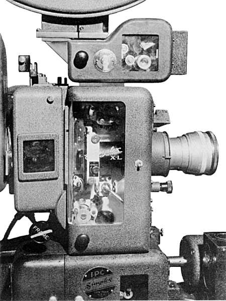 FIG. 10
 FIG. 11