The Evolution of the Williamsburg System:
Motion Picture System from Camera to Viewer
By BEN SCHLANGER
The following, the second of two articles on the planning and construction of the twin motion picture theatres at Colonial Williamsburg, appeared originally in the Journal of the Society of Motion Picture and Television Engineers. The Editors of International Projectionist gratefully thank SMPTE for permission to reprint the Williamsburg Story written by Arthur L. Smith, Williamsburg audio-visual director, and architect Ben Schlanger of New York. In this second article on the planning for the theatre system, Mr. Schlanger is the author.
The proposal for a very special type motion-picture presentation for Colonial Williamsburg specified a practical and economical system that would be able to project an illusion of reality beyond that of a conventional "movie." The effect, as nearly as possible, would be that of living re-enactment of events just prior to the American Revolution.
Also the presentation to the visitor to Colonial Williamsburg had to be unusual, differing from all of the comparatively new types of film projection being introduced at about the time this program was started.
If Cinerama, CinemaScope or even just the most modest wide-screen developments, all comparatively new at the time, could have been exclusively used by Colonial Williamsburg the problem might readily and quickly have been solved. But we had to have something more than any of these systems could achieve and we had to accomplish it without any radical changes in any of the equipment, optics, or film developed to this time.
We chose to use available equipment and processes in a new way to take advantage of this unique opportunity. Our goal was to build a theater and to produce a film, using the greater film area per frame available, that would enable the viewer to feel that he was "at the scene" and participating in the events shown on the screen.
For this "illusion of reality" it is necessary to have "picture dominance," sufficient resolution of photographic detail and a suitable cinematographic technique. The first reaction to these specifications from the motion-picture industry was discouraging, the general attitude being that it was too much to expect that a motion-picture film could be made to be shown only in a specific theater or that a theater could be specially designed for a given film. The Colonial Williamsburg project was to be the first example of such a coordinated and related procedure to achieve this end result. In Colonial Williamsburg we found the first opportunity to plan the theater and the film to be shown in the theater and to profit thereby from all of the advantages presented by this combined effort.
Frame Area and Seating Capacity
The availability of a film area per frame greater than the amount obtainable with standard 35mm projection was the first requirement in this project. The film dimensions for the VistaVision frame are shown in Fig. 1. It should be noted that by using the small perforations, six 50-mil soundtracks, one each outside and two inside, are available and since these are running at 180 ft/min, rather than the usual 90 ft/min, a 100-mil track equivalent (to single-frame sound) is obtained.
Fig. 1. Magnetic track positions for six channel sound on VistaVision prints.
(Courtesy of Paramount Pictures Corp.)
With this new film presentation technique there is a definite relationship between the film area per frame and the possible seating capacity of the theater auditorium. The film area per frame of standard 35mm projection would have yielded insufficient seating capacity.
Seating capacity is determined in this case by the minimum and maximum viewing distances and the width of the viewing pattern. In turn these dimensions are determined by the size of the projected picture which in turn is determined by the film area per frame, the projection optics and the projection light available. The horizontal VistaVision projection system used in this project made it possible to project a picture of good quality 52 ft. wide and 26 ft. high which could be viewed from a distance of 33 ft. or more without revealing film grain or fuzz. The bottom of the projected picture was placed at a level approximately even with the floor under the first row of seats so that the top of the picture would not be unnaturally high for the first row of seats and yet high enough so that the top edge is not too easily visible to any of the entire audience.
The vertical and horizontal range of vision was studied to aid in determining the proper position for the top of the projected picture and the maximum viewing distance, limited by the vertical and horizontal angles within which one could see without being aware of head or eye movement. This range was selected as the range within which most of our visual experience time is found. The horizontal range was found to be approximately 60° and the vertical range about 15° above the true horizontal level. The "picture dominance" effect is possible when the top margin and side margins of the projected picture are positioned so as to fill the whole range of vision described by these angles. This in turn enables the viewers to have the walls and ceiling of the auditorium enclosure beyond their easy range of vision, and usually when the viewer is concentrating on the performance the head does not turn to see beyond the picture area.
The Screen
Some detailed consideration may now be given to the screen before describing the viewing area and the projection facilities.
The giant 120-ft. screens are the result of considerable original research by the authors of these papers who tested almost every known screen material with many variations of surface and gain in an attempt to find a material which would have the desired amount of reflectance and which, in the extensive and curved surround portions, would be properly sympathetic in reaction to reflections from the projected image area. Embossed screens were of particular interest but none of these could handle the light perfectly throughout the entire curvature of the screen. As a matter of fact, neither could the standard aluminized surfaces until graded spraying was introduced.
The projection area extends from floor to ceiling; therefore the screen must extend beyond these extremes. Without the elimination of the vertical supports, it would be necessary to thread the huge one-piece screen between the upright members-a procedure which probably would have distorted the flexible plastic. With a frame devoid of vertical supports, the actual installation was accomplished in less than six hours.

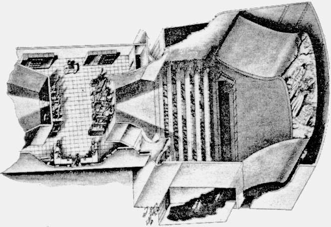
Fig. 2. Isometric drawing of Williamsburg Center Theaters. Note entrance area at bottom functions as light lock. Light level adaptation can occur in this passage.
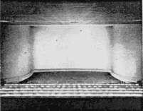
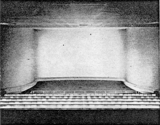
Fig. 3 The theater seen from the rear shows the illuminated barrier walls and the curvature of the screen.
As may be seen in Figs. 2 and 3 the curvature of the screen was to be complex, probably more complex than any ever attempted elsewhere. It is two modified S curves and there was considerable doubt that a screen could be hung in this manner without wrinkles and extensive bellying; however full-scale tests engineered by Selby Industries at Cleveland demonstrated the feasibility of the idea.
In the final installation the screen was stretched on a pipe frame that threaded through adjustable brackets, thereby permitting the desired curvatures. No vertical members were used in the frame. The top brackets were fastened to the ceiling and the bottom ones to the floor. This was highly desirable because the screen, being higher than the ceiling, had to be unrolled from the back.
Although the screen image was to extend to the full screen height of 26 ft., the horizontal measurement was to be only 52 ft. at which point it was to blend into a continuing screen surface surround. The blend was accomplished initially by having the outer rays of the projected image meet the screen at its point of greatest curvature.
However, the print of the transition and surround, area proved to be too reflective when coated with 1.7 gain necessary for the image area. Blended spraying reduced the surround gain to a desired 1.3 and this proved to be quite satisfactory.
A maintenance procedure which may prove of interest to others is the practice of removing dust accumulations on this large screen by means of hand rollers covered with soft, disposable felt.
Design of the Viewing Spaces
The 60° horizontal range dictated a maximum viewing distance of about 61 ft. which permitted eight rows of seats liberally spaced at a distance of 4 ft. The very low position of the bottom of the picture also made it appear that the picture filled all visible space. The liberal row spacing was needed to permit quick ingress and egress for the continuous change of audience every 40 minutes. With all of these requirements we were able to develop 240 seats in the seating pattern, restricting the width of the pattern to about 5 ft. greater width than the projected picture, and so avoid a distorted view of the image from extreme side seats.
Fig. 4. Plan of the theater (Courtesy of Architectural Forum)
The number of visitors anticipated for the performance was calculated to be 500 every 40 minutes or 500 per showing of a 40-minute film. This requirement had indicated the need for two separate viewing spaces and this duplication was readily accepted because it also made it possible to stagger the starting times of the showings so that a showing could start every 20 minutes. As Fig. 4 indicates, a single projection room was placed between the two viewing spaces with a complete set of projectors for each screen of each viewing space. To provide sufficient projection distance for a 52-ft. projected picture and yet be able to use an acceptable projection lens it was necessary to increase the projection from the screen to a point beyond that which would otherwise have been suggested by the position of the row furthest from the screen. This requirement increased the total length of the structure with the resultant extra space being used for a much needed foyer and exhibition area under the viewing spaces.
As noted above these viewing spaces are designed for films made specifically for showing in these viewing spaces and in none other. For example, because the projected picture is so large for the dimensions of the viewing pattern it becomes unnecessary to use more than one focal length for the cinematography. Short focal length lenses producing the so-called close-up shot are deliberately avoided because satisfactory visual acuity is assured with the limited viewing distances. Also, the figures of people and objects are kept in a relatively lower and more natural position on the screen with a medium focal length lens. Another requirement is to keep figures of people and objects somewhat away from the top and the sides of the screen so as to provide a much needed peripheral area beyond the main points of interest of a given shot. Important detail is kept away from the marginal areas of the picture so that these areas can be used for a vignetting and blending of the picture into walls and ceiling contiguous and continuous to the screen. These transitional areas are seen only out of the corner of the eye because of the seating pattern design and the walls and ceiling are seen only if a viewer turns his head deliberately away from the normal viewing direction. Even if such an unusual turn of the head is made the blending of picture and picture surround is soft and not in any way distracting. This is accomplished by having the screen surface continue into the surround with the same color and texture as the screen and also by controlling the amount of light re-reflected from the screen from this surround area.
With the screen filling the entire space from floor to ceiling, no curtains or contrasting frame maskings are used. Instead of the usual structural walls on either side of the screen, the screen material itself continues to become the screen surround. There is no room for any artificial "picture-on-the-wall" effect. It is even possible for the viewer to become oblivious to the space enclosure where he is sitting as he becomes more absorbed in the screen. Another step toward bringing about the illusion of reality and heightening viewer participation was that of concealing the presence of other viewers and making sure that the traffic aisles would not be visible. Low walls were built to conceal other viewers while not obstructing the view of the projected picture, and traffic aisles along the extreme side seats are out of view (Figs. 5 and 6).
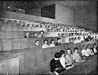
Fig. 5. Eight rows of seats are separated by barrier walls.
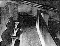
Fig 6. Continental seating and generous aisles are illuminated from below seats.
Barrier walls between seats are also illuminated.
Each row of seats is elevated sufficiently above the preceding row to assure unobstructed vision of the projected picture over the low walls. The entrance and exit doors to the viewing spaces are located so that they do not appear within easy range of vision when the projected picture is on view. There are no secondary sources of light visible for room lighting during the picture projection period. Sufficient light for safety purposes comes from the screen itself and from low-level carpet lighting in the side aisles which does not show to the viewers' eyes. During the emptying and filling periods the viewing spaces are illuminated with an overall skydome effect by concealed flood light and concealed lighting within the low separating walls between the rows. These walls are plastic-lined perforated stainless steel to enhance the effect of floating in a uniform and evenly lighted space. From these viewing spaces there is no way of measuring distance to the screen because there is no yardstick of visible people, furniture pieces or architectural elements or even differences of shading of light to serve as clues for sensing distance. This feeling carries into the picture projection period. Care was taken even in the selection of the texture of all surfaces to be sure that all light would reflect evenly from all surfaces.
Projection Booth
The basic size of the booth is 50 by 50 ft., but part of this is lost in front of the projection machinery where it becomes a "throat" into the theaters. It is large, clean, acoustically treated and air-conditioned (Figs. 7 and 8).
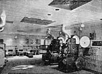 Fig. 7. Each theatre is equipped with two VistaVision projectors and one 16mm arc projector. Also available are 2 x 2 slide projectors and a standard 35mm projector.
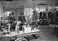 Fig. 8. The rewinds in the foreground accommodate such large reels that special consideration was given to the torque problems of the rewind motors.
Four horizontal VistaVision projectors are the principal equipment in the booth, with two facing into each theater. In addition, each theater has a 16mm Eastman Model 25 Arc Projector and a double slide projector equipped with an optical dissolve mechanism. The VistaVision projectors are generally standard but do have some important modifications. Curved gates and larger intermittents and sprockets carry the film better. The Brush soundhead picks up the sound signal ahead of the picture Special reels, 28 in. in diameter, carry the entire 37-minute show and require 30in. magazines. Half-inch spindle shafts are used.
The relatively short projection throw required the use of a 2¾-in. lens and the Bausch & Lomb Super Cinephor which was chosen has been quite satisfactory. Optical problems resulting from the use of a short lens and a condensor type lamp resulted in a shift to mirror-type lamps. The mirror-type lamp enabled an amperage reduction from 180 to 135 amps. Ashcraft lamps, modified slightly, produced a flatter field of better quality light. Three trims were obtainable from a carbon, instead of one, at 180 amps.
A design for maximum lamp to screen efficiency led to the elimination of glass in the booth portholes. Since the double-speed VistaVision projectors make more noise than the single-speed variety, it was necessary to design an acoustic hood for the area between the projector and the port. This was designed by the firm of Bolt, Baranck and Newman.
The projectors are powered by d-c generators and three 300-amp units are on call. When the lamphouses were changed from condenser-type to mirror-type and the power for each machine reduced to 135 amp, only one generator was necessary at a time and this has enabled the other units to be rotated and serviced for maximum efficiency.
The rewind area of the projection booth contains two torque-motor-driven rewinds. They are installed on low tables at which operators can sit comfortably during the rewind and inspection process. A Bell & Howell pedestal-type hot splicer is located midway between the two rewind tables.
The storage of the oversized reels of film was a problem which was nicely solved by placing them in slightly ramped compartments. When the narrow door of a compartment is dropped to become a supporting rest, the reel of film, via simple gravity, rolls forward to a cushioned stop and can be easily picked up by the operator and taken to the projector. The total weight of reel and film (6600 ft.) is 42 lb.
All booth wiring is located in large accessible recessed floor and wall conduits. Of particular interest are the control stations provided conveniently beside each machine (Fig. 9). Within these control stations are housed complete master operations including:
(1) all necessary on-off switching,
(2) automatic segues from one sound source to another.
(3) a master up-down pushbutton set to control all lights.
(4) cue and voice signals from the stage area, and
(5) time clocks which reset by lever action.
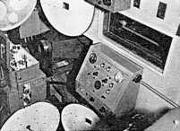
Fig. 9. The control stations beside each machien are thought to be unique. With the exception of firing the arc, all controls are at this staion including rmote stereo tape for intermission, motor start, master button for dimming circuits, automatic sound segue, program timing, stage communication, etc. To the left of the control station are the acoustic hoods which snug up against the projector when in use. This device permits glassless ports.
Much of the automation included in the central controls is valued because it eliminates the human variation which occurs in such operations as manual fading. The motor-driven automatic segue takes place in about four to five seconds and provides a smooth transition blend of sound. Although the idea for this came from Mr. Smith, the actual design of the unit and other specialized Altec installations are to be credited to Dave Demarest of that firm.
Each theater has available a two-track Ampex stereophonic tape machine for intermission music and the sound output normally is fed to behind-the-screen speakers Nos. 1 and 5 (the outer units). The Ampex-type units can be started and stopped remotely at the central control station.
The control stations are important both in terms of innovations and logic. In the vast majority of theaters in operation today, control points tend to be scattered all over the booth. All too frequently intermission music is obtained from turntables and scratchy records. High-quality sound from tape is certainly better and seems to be appreciated by the audience.
Audio monitoring of the six-track} film sound is also available when the operator is standing at the control station. Each track may, if desired, be monitored separately.
The main amplifier banks include spare circuits and plugin components which enable rapid switchovers when trouble occurs.
Each of the two theaters contains a public address system which has amplifiers and speakers separate from the film sound equipment.
It may also be of interest that each theater was provided with a Budelman wireless microphone setup. It was necessary to replace the antenna provided with a conical TV type in order to obtain best results.
Inasmuch as the theaters are used during the evening for presentation of special lectures, provision for the use of slides was necessary. Two Strong Arc Projectors with a dissolving mechanism and automatic picture feed were assembled by W. A. Yoder of Richmond, Virginia. The Ampex stereo machines also supplied by Mr. Yoder. have a special provision whereby when used to play a prerecorded talk on one track, can provide a signal from the other to activate the automatic feature of the slide projectors. Hence a complete show can be presented automatically and the frequency of slide changes need not be fixed interval.
Outside of the entrance door of each theater is a time signal in minutes which shows the number of minutes before the next show begins. The starting digits can be dialed from the booth and clock action reduces the numbers.
Both entrance and exit doors operate automatically when patrons approach under-carpet switches.
Lighting
The theaters are equipped with complex automatic dimmer systems wherein different areas of lighting can be preset and the whole can be controlled by a single pushbutton located at control stations. There are "light adjustment locks" which the visitor passes through on his way from the brilliantly lit lobby to the theater interior, and these provide a partial adjustment in level. During the performance these are faded out. At present only two principal light sources are used for auditorium lighting. One is strip lighting beneath the seats which also illuminates the barrier walls between the rows. The second is screen floodlighting. The latter has available three primary colors plus white spotlighting where patterns may be projected. Rear cove lighting and ceiling spots are used on other-than-film occasions and panic lights are available for emergencies and cleaning.
Although this complete facility is used at one time or another, the standard choice for intermission screen lighting has been "unearthly blue which suggests a mystic mood. Many people entering the theater for the first time see no screen at all-just a soft haze of blue light.
As the lights are dimmed, a film image appears and the audience is in a dense forest. Only the sound of twittering birds is heard. The camera dollies towards a small bright opening through the trees and as the bright image grows larger and larger it reaches the full 52-ft. size—an awe-inspiring sight.
No titles or credits are projected on the screen. These are shown in an illuminated showcase permanently located in the lobby.
Conclusion
The desire in the designing was to permit the viewer to the fullest possible extent to be able to transport himself in imagination to a different time and space by furnishing a floating void or optical vacuum to provide the transition to the new time and space and to hold him there by eliminating all distractions. The name Transcenium suggests itself for this type of presentation. Long light locks having intermediate light levels serve as a transition from conditions of the outer foyer to the special spatial effect of the viewing enclosures.
Larger seating capacities are possible with this type of presentation by using still greater film area and using a less commodious seat row spacing. It would be possible to project a good-quality picture 63 ft. wide with 70mm film and thereby provide about 400 seats on either side of one projection room. The combined seating capacity of 800 seats for such a transcenium presentation would, it is believed, bring a fuller enjoyment to more film fans.
|